Pi Retro Handheld
March 15, 2024

A lot of us have grown up playing video games. The sheer joy and happiness they brought to our childhood is something we often look back upon. Sometimes we get nostalgic and want to experience these games again. For me, many of the games I played during my childhood were Nintendo games, even though I was unaware of the existence of Nintendo, which I would come to know many years later. The first console I got was a Famiclone, which was simply called "Video Game" locally, and you had to hook it up to the composite input of a TV. I used to play games like Super Mario, Duck Hunt, Contra, Battle City, etc. Then, when I got a computer, I played games like Super Mario World, Pokémon Emerald, Pokémon Black, etc. At the time I had no idea that they were console games or that I was emulating them.
So, to cut to the chase, I love retro games as they have been a huge part of my childhood. Naturally, I want to play them from time to time, and the best way to do so is to play them on genuine hardware. However, that can be very expensive especially the games and the absurd import tax rates in my country add further to that. So, the next best thing is to buy one of those handheld emulators like the Miyoo Mini, but again, the absurd import tax and a ban on most Chinese e-commerce sites in my country make it very expensive and hard to buy an otherwise reasonably priced console.
So, is emulation on PC or mobile the only option? Well, not quite. There is another option, which is to make our own emulation handheld console. Making our own console—won't that be very complicated to do? Well, not quite. My Goal is to make:
- Something that can emulate systems like NES, SNES, GBA, GB, GBC, PSX, etc. And for me personally NDS (for some Pokémon).
- Considering those systems, the display resolution should be at least 240x240.
- Enough buttons for all systems and at least one hotkey button for RetroArch.
- Portable and battery-powered.
- HDMI out.
- Should use off-the-shelf components.
- Must be low cost (up to $60).
First, let's start with the brain. For that, we are going to need a SOC, and the best way to use SOCs is with SBCs. What better SBC for this project than the good old Raspberry Pi.


Ever since the Raspberry Pi Zero 2 released, it was always a compelling option to me since it basically has the power of the Pi 3 in the form factor of the Zero, so it’s more than enough for the systems I want to emulate.
Now that the SBC is chosen, let's move on to the display. We need a display with at least 240x240 resolution. My first option was to use a ST7789 SPI IPS 240x240 display. It is excellent for this application and you can even find ones which are OCA laminated for less than $5. However, the only issue with this display is its small size. While some people might claim the size to be more than enough ahem ahem, the 1.54" display is not going to cut it, for a pleasant gaming experience we need a larger display. Then I tried the ILI9341, which has a resolution of 320x240. It comes in sizes of 2.4" and 2.8". These sizes are much more pleasant to play games on. The only caveat is that the display is not IPS and has pretty bad viewing angles horizontally. Another issue with this display is that due to its common nature, the display’s color vibrance, viewing angles, etc. vary from display to display. So unless you buy from a trusted manufacturer, there is no way to tell what the quality of your display will be. Even though the ILI9341 has so many caveats, I ended up choosing it due to the price and the limited selection of displays available in this price/size range.
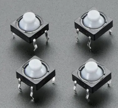
Now we have chosen our display as well. Now let's move to the buttons. Firstly, how many buttons do we want? I settled on a D-Pad (UP, DOWN, LEFT, RIGHT), A, B, X, Y, L1, R1, START, SELECT, HTK1 (L2), HTK2 (R2), HTK3, so 15 buttons in total. For the buttons, I decided to go with soft silicone 8mm push buttons as they provide a soft tactile feel which is quiet satisfying.
Now, how do we drive these buttons and use them to play our games? My first option was to use a microcontroller with HID support and then use it as an external controller, but due to the size constraint, that was not possible. I decided to use the Pi GPIOs directly. I found 2 great drives for this, one is GPIONext and the other is Adafruit's Retrogame. I went with Retrogame as GPIONext was using a significant amount of the CPU, which caused stuttering in certain emulators and higher battery drain.
Moving on to audio, since the Pi Zero variants have no built-in DAC, we have to improvise. There are four ways to get audio from the Pi Zero:
- HDMI
- External USB DAC
- PWM Audio
- I2S DAC
- HDMI Audio only works with a HDMI screen.
- The External USB DAC is very bulky and takes up the only USB port on the Pi.
- PWM Audio has background static noise and requires a filter.
- i2S DAC's require 3-4 GPIO's and are relatively more expensive.
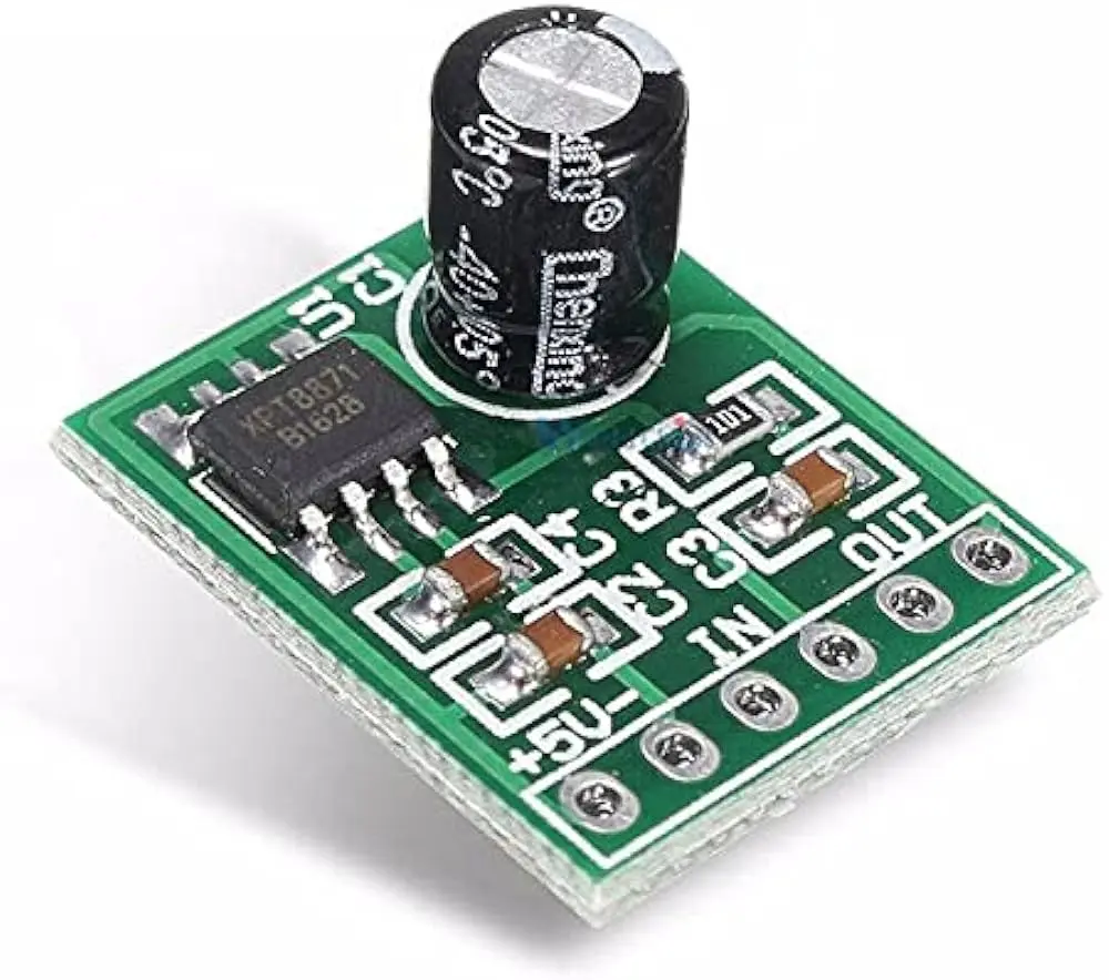

I settled for the PWM Audio option since it requires no special hardware and is very cheap. For the amplifier I went with a XTP8871 5W mono amplifier and for the speaker i went with a 18mm 1W round speaker.


Now, moving on to the power and the battery section. For the battery, any decent capacity LiPo can be used. I used a 3.8V 2300mAh LiPo as I had it lying around. For supplying the Pi with 5V, charging, and managing the battery, I used a Type-C USB 5V 2A Step-Up Boost Converter based on the IP5306 IC, which supports both 3.7V and 3.8V LiPo/Li-ion batteries and can supply more than enough current for all the components.
With the electronics side done, now we need to focus on the case. I wanted to 3d print the case so I started with the PIRAKEET case as a base and, with heavy modifications, turned it into more or less what I had in mind.
The case has four main parts: The Front, The Back, the Buttons and The Volume Wheel.
Now that the hardware and the case are done, it’s time to make a BOM (Bill of Materials) and start the assembly.- Raspberry Pi Zero 2 W x1
- 14mm heatsink for Raspberry Pi x1
- SD Card x1
- ILI9341 2.4" LCD x1
- IP5306 Boost Converter module x1
- XPT8871 Amplifier module x1
- 18mm 1W 8-ohm round speaker x1
- 8mm Silicone push buttons x8
- 4.3mm push buttons x7
- Perf board x1
- 6mm vertical slide SPDT switch x1
- 2300mAh 3.8V LiPo x1
- 10k trimpot x1
- 270-ohm resistor x1
- 150-ohm resistor x1
- 10µF Electrolytic capacitor x1
- 33nF Ceramic capacitor x1


The parts were assembled into the case as shown in the above pictures.
Finally onto the software, we have many options. We can use the stock Raspberry Pi OS and then install RetroArch on it, or we can use OSs specifically tailored for retro gaming, such as RetroPie and Recalbox. I went with RetroPie, mainly cause it has DraStic built-in, which is the best DS emulator out there. After flashing the RetroPie image onto my SD card and booting into RetroPie, it was time to set up all the software and drivers.
Display Driver Setup:
- In RetroPie settings, turn on SSH.
- Connect to a Wi-Fi network, check the IP in RetroPie, and SSH into the Pi with PuTTY (default username is "pi" and default password is "raspberry").
sudo passwd rootusermod -aG sudo pisudo apt-get install build-essential cmake pkg-config
		cd
		sudo git clone https://github.com/juj/fbcp-ili9341.git
		cd fbcp-ili9341
		sudo mkdir build
		cd build
		sudo cmake -DILI9341=ON -DGPIO_TFT_DATA_CONTROL=24 -DGPIO_TFT_RESET_PIN=25 -DSPI_BUS_CLOCK_DIVISOR=6 -DDISPLAY_ROTATE_180_DEGREES=OFF -DGPIO_TFT_BACKLIGHT=26 -DDMA_TX_CHANNEL=2 -DDMA_RX_CHANNEL=5 -DSTATISTICS=0 ..
sudo make -jsudo nano /boot/config.txt#dtoverlay=vc4-kms-v3d
		hdmi_group=2
		hdmi_mode=87
		hdmi_cvt=320 240 60 5
hdmi_force_hotplug=1sudo nano /etc/rc.localsudo /home/pi/fbcp-ili9341/build/fbcp-ili9341 &
		cd
		cd /fbcp-ili9341/build
sudo ./fbcp-ili9341sudo reboot nowButton Driver Setup:
		cd
		curl https://raw.githubusercontent.com/adafruit/Raspberry-Pi-Installer-Scripts/master/retrogame.sh >retrogame.sh
sudo bash retrogame.shsudo reboot nowsudo chmod +rwx /usr/local/bin/retrogamesudo nano /boot/retrogame.cfg
		ENTER      3  # A
		BACKSPACE 22  # B
		SPACE      2  # X
		LEFTSHIFT 17  # Y
		UP        15  # Joy Up
		DOWN      14  # Joy Down
		LEFT      16  # Joy Left
		RIGHT      7  # Joy Right
		A          5  # Start
		B         27  # Select
		C         20  # L1
		D          6  # L2
		E         21  # R1
		F          4  # R2
		G         23  # HotKey
PWM Audio Setup:
sudo nano /boot/config.txt
		dtparam=audio=on
		dtoverlay=audremap,enable_jack
		dtoverlay=pwm-2chan,pin=18,func=2
Go to raspi config and in the Audio section find the ID for "headphones". It should be either 0 or 1.
cd /usr/share/alsa
		sudo nano alsa.conf
Set the values for defaults.ctl.card and defaults.pcm.card to the ID of "headphones".
sudo reboot nowsudo aplay /usr/share/sounds/alsa/Front_Center.wavWith that, the software setup is complete. I tested everything and closed the case.

And finally complete, my very own emulation handheld, which can emulate a ton of systems and is feature-packed. Some features include HDMI output, Wi-Fi + BT support, OTG support, and much more.Initially, I had set a cost constraint that it should cost no more than $60. So, how much did it cost to make? Let’s see:
- Raspberry Pi Zero 2 W: $16
- 14mm heatsink for Raspberry Pi: $1
- Buttons: $4
- SD Card: $5
- ILI9341 2.4" LCD: $5
- IP5306 Boost Converter module: $1
- XPT8871 Amplifier module: $1
- 18mm round 1W 8-ohm speaker: $1
- 2300mAh 3.8V LiPo: $5
- Passive components: $4
- Perf board: $1
- 3D printed case: $4