Pixel Art Display
July 25, 2023
I've always been fascinated by LEDs, and one of the most exciting applications I can think of for them is assembling them into giant displays. Sure, the resolution might be very low, but the resulting display is one of the best ways to showcase pixel art or simple statistics, even in broad daylight, thanks to its superior brightness and vibrance, which even modern OLEDs and LCDs can't match.

However, the issue with such displays has always been the cost. The simplest way to make them has been to use addressable LEDs like Neopixels and to daisy-chain them together. But even the cheapest clones of addressable LEDs can become very expensive in the large quantities which are required to assemble a full display. So, for a while I had given up on the idea of making such a display due to the associated high cost.
Then, one day while browsing AliExpress, a listing caught my eye. The listing was labeled as "r̶e̶d̶a̶c̶t̶e̶d̶ c̶o̶m̶p̶a̶n̶y̶ n̶a̶m̶e̶ 64x64 WIFI Pixel Art Display." My eyes couldn't believe what I was seeing: a full-blown LED display with a whopping 4096 RGB LEDs, all packaged into a nice, slim case. But this excitement soon faded as I glanced at the price, $163! Like what was I expecting? With so many addressable LEDs, of course the price was bound to be this high. Or was it?
Even after giving up on buying the commercial pixel art display, the thought of how they powered so many LEDs never left my mind. So, bored one day, I did some research about the company producing them, and sure enough, a website popped up with many more LED pixel art displays of varying resolutions. 16x16, 32x32, and the highest one being the 64x64 one. After looking at the product specifications, I was shocked to see that the current for the 64x64 display was just 2A at 5V, which is just 10W for 4096 LEDs! leaving me even more confused.
So, I started looking for some teardown videos of these displays, but sadly, I couldn't find any. Then, I noticed that the displays were FCC certified, which gave me an idea.
The thing with FCC tests is that almost all of the certificates and tests are publicly available on websites like FCCID, which most of the time also includes teardown photos.


So, after getting a hold of these photos, I made a discovery: the LEDs were indeed not addressable but normal RGB LEDs driven with a dozen LED drivers, multiplexers, and shift registers which explained the low power consumption. The display was driven by an ARTERY AT32, which is an STM32 clone, and the Wi-Fi and data part was handled by an ESP32. Initially, I thought that an ESP32 was sufficient to do both tasks at once, but soon I was going to find out why they had gone with this approach.
Now I had a rough idea of how such a pixel art display worked, but I was still unsure about how I was going to obtain the LED panel itself. Making such a panel from scratch was not an option due to its sheer complexity, the component count and the PCB size itself would have been very expensive to manufacture in small batches. So looking for a premade product was my only option.
One day while traveling, I saw some technicians installing a LED advertisement board. What I found surprising was that the display was made up of smaller panels. I walked up to them, asked them about the panels, and took a look at one of them. They were surprisingly similar to the ones used in the commercial pixel art display.
After asking the technicians some questions, I found out that:
- They come in various resolutions.
- They can be either weatherproof or non-weatherproof.
- They are called HUB75 Panels.
Upon googling, I found a ton of these panels of varying sizes and resolutions, and the best thing was that they were pretty cheap. So without wasting any time I bought two of these panels, one 64x64 and one 32x32.


In the meantime, I started doing research on how to drive them. With hundreds of panel variations and no datasheet references, it was going to be a difficult job. Then, I found an excellent article from Sparkfun detailing the working of these panels.Sadly, the 32x32 panel I bought was a 1/8 scan one which is a bit more complicated to use so I set it aside for the moment and focused on the 64x64 one, which was a 1/32 scan, which is much more common and easier to work with.
I started by writing my own library, but the results were disappointing to say the least which was probably due to a skill issue on my end. The approach of using a single microcontroller to handle the display, the wireless connectivity and GIF decoding was not looking feasible and I had come to realize why the commercial pixel art display had used 2 separate microcontrollers.But just when I was about to give up I found a golden goose, a library written by MrFaptastic to drive HUB75 panels via DMA through the LCD mode of the ESP32. This was game changing stuff, now I had all the tools at my disposal and now was the time to put everything together.
My goal was to:
- Drive the panel with a single ESP32 and use it for other peripherals simultaneously.
- Upload and play simple animations to the display.
- Make a Web UI to manage the panel and the animations.
- Have room left to add further features in the future.


First of all, the panel uses 6 pins for the color (2 for each channel), 5 pins for displaying the data,and other 3 pins for panel control. This is a lot of GPIOs being used, but due to the abundance ofGPIOs on the ESP32, it shouldn't be an issue.
The schematics are as follows:
- HUB75 PIN-->ESP32 GPIO
- R1 PIN --> GPIO 25
- G1 PIN --> GPIO 26
- B1 PIN --> GPIO 27
- R2 PIN --> GPIO 14
- G2 PIN --> GPIO 12
- B2 PIN --> GPIO 13
- A PIN --> GPIO 22
- B PIN --> GPIO 32
- C PIN --> GPIO 33
- D PIN --> GPIO 17
- E PIN --> GPIO 21
- OE PIN --> GPIO 15
- CLK PIN --> GPIO 16
- LAT PIN --> GPIO 4
- GND PIN --> GND
And in order to have future compatibility with this project, don't use GPIO 5, 23, 18, 19 as I have reserved them for an SD card, which will be added in the future.


Since the HUB75 Panels use a 16 pin IDC connector I glued one on the back of the ESP32 and wired that up according to the schematics and used a 16 pin female IDC cable to connect the ESP32 to the HUB75 panel. This way you can test multiple panels with the same ESP Controller since the HUB75 pinout is universal for all panels.
Now the hardware was set up, and I tested the panel with the example code from the library and modified it according to my hardware config, and it seemed to work.
Now it was finally time to write the firmware.
We need to play animations on the panel, but first, we need some way to store them on the panel. We have a few options:
- We can convert video files into simple images and then convert them into hex arrays or RGB values, but this was messy, time-consuming, and required an external program and several processing steps.
- We can convert the video into BMPs and read them, but this method uses a lot of space.
Now the first part of the problem was solved, now all I needed was a way to upload these GIFs to the panel wirelessly and manage the panel and the files on the SPI Flash.
For this, I chose the simplest solution, which was to write an ASYNC web server and to host a Web UI with it, which could be accessed through the web browser of any device on the same network. This eliminated the need for an app and made the display plug and play.
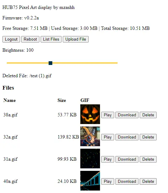
The features I added to the web UI were:
- Ability to upload, delete, and play GIFs stored on the SPI Flash of the ESP32 via Wi-Fi.
- Control the brightness of the display.
- Ability to check the Flash storage stats.
- Ability to remotely reboot the ESP32.
- An AUTH function, which required a password to access the panel web UI.

For ease of use, when the panel is powered on, it connects to the Wi-Fi network and shows the firmware version, IP address, RSSI, and Wi-Fi SSID for 4 seconds.
Now the firmware for the panel was more or less done and it was time to move on to the case for the panel.The case needed to be:
- Slim.
- The electronics should be accessible since the project is still in a beta phase.
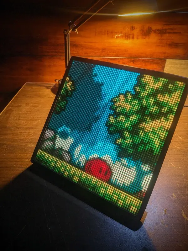
- Most importantly, it should incorporate a diffusion layer and a diffusion grid, which should give the display a distinct pixel art like look

So, I designed the case in Fusion 360, taking heavy inspiration from Adafruit's LED matrix case, and 3D printed them on my Ender 3. It all turned out fine except for the diffusion grid. The tolerance for the panel is 1.5mm between each LED, so even small imperfections in tolerances would result in the grid not fitting the panel, as the imperfections are multiplied for each of the 4096 LEDs, which my Ender 3 couldn't handle and the printed grid would not fit on the panel.
So in order to solve this, I divided the grid into 4 parts and printed them separately. I positioned them on the LED Panel and they fitted near perfectly. If you have a better 3D printer or a laser cutter or a CNC, you can make a much better diffusion grid than I have and print/mill it in one go with tighter tolerances.
M3 nuts and bolts are required to secure the feet to the cover.
The case should assemble in the order: Cover <--- Feet <--- Glass/Acrylic <--- Diffuser Sheet <--- Diffusion Grid <--- HUB75 Panel <--- Frame <--- ESP32


Now selecting the proper diffusion material was a challenge in itself. I tried a variety of materials like wax paper, a white tablecloth, translucent acrylic, but they all had issues, either they didn't diffuse the light evenly enough or the light output was significantly reduced. At last I tried a sheet of tracing paper, and it worked wonderfully for this application.
Finally it was time to put it all together and Finished!
But the question remained, Did I beat the commercial display in terms of cost? Well, let's see:
- The HUB75 panel was $25.
- ESP32 is $5.
- The 3D printed parts are $5.
- The glass and the diffuser sheet and other materials are $5.